If no menu
or buttons show
ensure you have
scripting enabled
Please give time
for menu to load


|
|
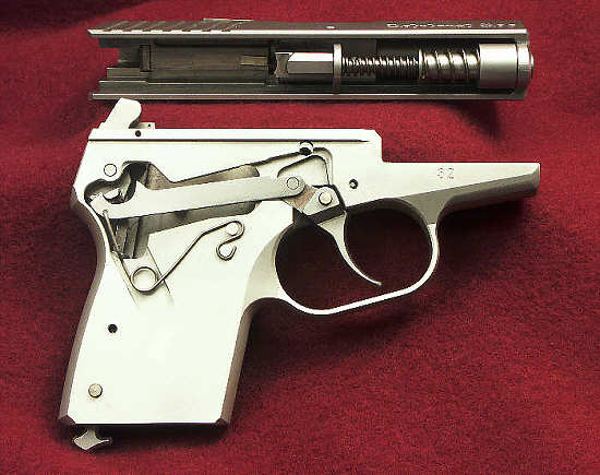
Further to the composite
picture taken from the owner's manual ..... the following
images show perhaps a little more detail and might
act as a useful adjunct when familiarizing with the
pistol.
|
|
After takedown by
removal of retaining pin ........ we have the complete
slide assembly (above) and below, the frame with
grips removed but trigger mechanism all in place.
The grips are currently retained with small screws
that require an Allen wrench of 1/16" size.
This should be a good quality item so as to be 0.625"
and not less.
|
|
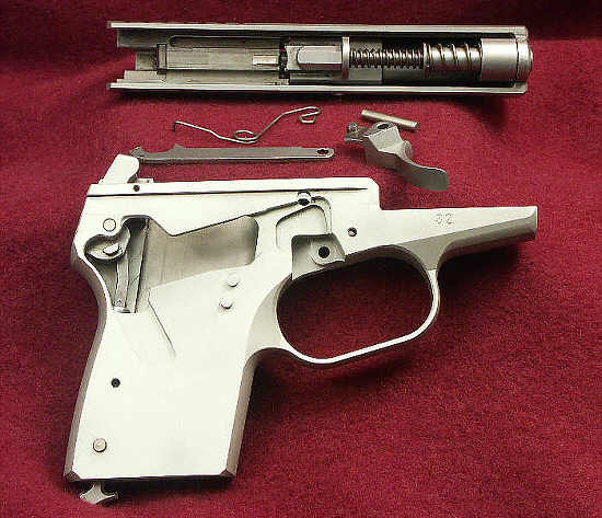
As previous picture
but now, trigger and pin are removed, along with
the transfer bar and associated spring. It is
this latter that is retained by right side grip
panel ... thus the reason for said panel not being
allowed to loosen.
I have not removed the hammer to save any problems
re-installing same and mainspring, but the mainspring
plunger is clearly visible.
|
|
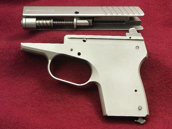
This is purely
to show a view of the left side of the frame.
Note, the left side of the slide has the larger
pin hole ... thru which pin removal is effected
by application of a punch (1/16") from
the right side (smaller hole).
|
|
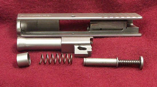
The slide alone
- all components except extractor and firing
pin are shown removed ..... thus, we have
barrel and, recoil assembly.
NOTE well ..... the mainspring MUST
have the formed end against the collar, and
the unfinished end within the end cup. Orientation
is as shown.
|
|
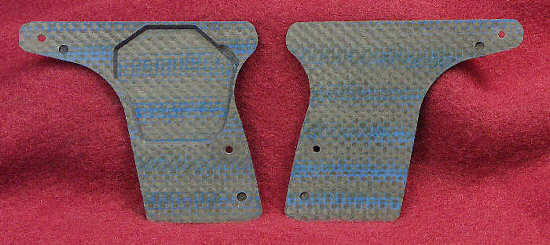
Carbon fiber
grip panels removed and showing internal
surfaces. The right panel of course is relieved
to accomodate the trigger transfer bar mechanism.
|
|
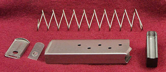
Finally
- a broken down magazine to show component
parts. Stripping down of a magazine should
not be required at all often, unless there
has been ingress of dirt etc ... when
of course scrupulous cleaning should be
done. I personally consider some lube
to be wise but kept minimal so as to avoid
attracting crud too much.
|
| The picture scanned
from the manual can be found here. |
|
Back to Top
|