|
Bob's test description
....
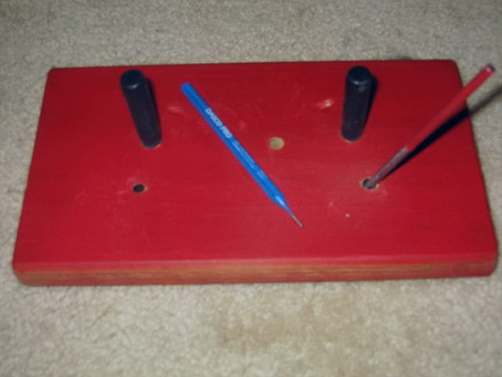
Basically, it is a board with two pegs to hold the
gun in place, a hole to receive the pin as it comes
out, and two holes to serve as anchor points for a
rod used to lever the slide back. See photos shown
below. This device makes pin removal and replacement
very easy.
After writing this, it occurs to me that using a spacer
(chopstick, etc) is really pretty easy and effective,
and I wonder how many R9 people will want to go to
the trouble of making this board. It does work well,
and once made, is good to have. A major advantage
is how easy it is to get the slide back and the pin
holes aligned for takedown. For me, it was an interesting
creative exercise.
I used material on hand, except for the rod. (Other
materials or sizes could be substituted)
Base: Decking plank, actual size 1 X 5 ½ X
9 3/4 ( 2 X 6 would be OK, just heavier). Pegs:
½ inch dowel (3/8 inch might be preferable).
Lever Rod: 3/16 inch steel, 4 1/4 inch long
(1/8" rod or 16d nail, 3 ½", is good ).
Everything was dipped or sprayed with Plasti Dip rubberized
coating (but it scratches easily)
The layout of my board works well for me, but for
someone else to build one, trying to replicate my
setup from a drawing without other info would be difficult,
particularly in placing the lever holes. So, I will
provide a combination of dimensions and description.
The layout should be checked with common sense as
you go through the process. I hope this is not too
much detail, but I do want to make it fairly easy
for anyone to follow.
Please excuse the mixture of measurement modes (16ths
vs tenths) -
Pegs: My ½ inch diameter dowel sections were
2 1/4 inches long; sanded a little at the bottom to
allow them to be driven about 1/4 inch deep into 7/16
inch diameter holes.
Left peg is 2.5 inches from top edge and 2.5
inches from left edge.
Right peg is 2.5 inches from top edge, and
4.4 inches, center to center, from left peg Right
peg location could be varied somewhat. It should be
in front of the ejection port, and far enough back
of the sight so it doesnt contact the sight when
the slide is moved back to align for pin removal.
Change of location for right peg will also change
location of pin hole and lever holes.
Pin hole: is 3/8 diameter, and is 2.6 inches
from top edge, and 2.7 inches, center to center, to
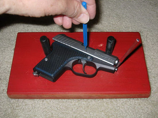
the right of the left peg. Before drilling, put chopstick
or other spacer in ejection port to have slide in
position to remove pin, then put gun in place as in
Photo 2, and verify location. Hole diameter is not
critical; 3/8 inch is convenient, but larger hole
would give more latitude for placement.
Lever hole: placement is important for good
operation of this take down tool. There are two ways
to get good placement. One is to use the drawing dimensions,
and do some trials with a nail as in No. 5 below.
The other is by the method described below.
If you have chopstick (or other spacer) to align slide hole with pin, insert
chopstick, place gun against pegs as in Photo 2, and then -
1. Draw line along front of slide, with line
on same vertical plane as front surface.
2. On that line, mark a dot, centered between
bottom of barrel and top of guide rod.
3. Remove gun.
4. Mark dot 1/16 inch in front of the dot (toward
lower right corner) from Number 2.
5. Verify location - - Drive 12d or 16d nail
in at this dot just deep enough to provide good purchase
to lever the slide. Place gun against pegs, and see
if this is good base location for lever to move slide
back and align pin hole. It may be necessary to raise
the muzzle slightly in order to start the slide movement.
If location seems right, drill.
6. Drill hole at that spot, about 1/4 inch
deep (1/4" drill for 3/16" rod; 3/16" drill
for 16d nail )
7. Use a round wood rasp to make a shallow
sloping groove, like a channel leading to the hole,
about 1/4 inch long, aligned with the direction the
gun points when in place against pegs. This will make
it easier to slide the lever rod into the hole with
the gun in place.
Or, if you dont have chopstick, place gun against
pegs, with slide in normal position, and then.
1. Draw line
along front of slide, with line on same vertical
plane as front surface
2. On that line, mark a dot, centered between
bottom of barrel and top of guide rod
3. Remove gun
4. From dot in No. 2, measure 0.31 inch (5/16
inch) in direction slide moves (toward upper right
corner); place dot (Actual slide movement to align
pin for takedown is about 0.35 inch (11/32 ))
5, 6, 7. Same as 5,6,7 above.
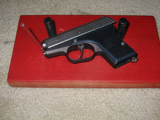
For the lever hole
on the left, put gun in place as in Photo 3, and use
same process.
Possible improvements:
Plasti Dip provides protective surface, but it
is already scratching and peeling.. Coating on
the lever rod got scratched up right away. Pegs
seem to be OK with the Plasti Dip.
Leather on the board would be good.
Lever rod without coating does not seem to mar
front of slide, but I prefer something other than
steel on steel (initially, I used duct tape on
a nail). Maybe aluminum rod, or plastic, would
work.
A change that could make everything much better
would be to replace the lever rod with a sliding
push rod acting along the axis of the slide. This
would have a cushioned end to contact the slide;
some way to easily apply the force needed to push
the slide back; and some way to lock it in position
when the pin hole in the slide is properly aligned.
It would also have to be duplicated on the left
side, or be moveable, from right side to left
side. |
|